IMX6 Ethernet. Development process to add second ethernet PHY IC support. part 2.
IMX6 Ethernet development process continuation. So after getting working single PHY IC on new revision of OpenWrt driven SoM we continue development process to get working two PHY IC on same PCB.
First of all we soldered second testbench that provides access to core functionality (JTAG, both ethernet interfaces and UART console) of SoM module:
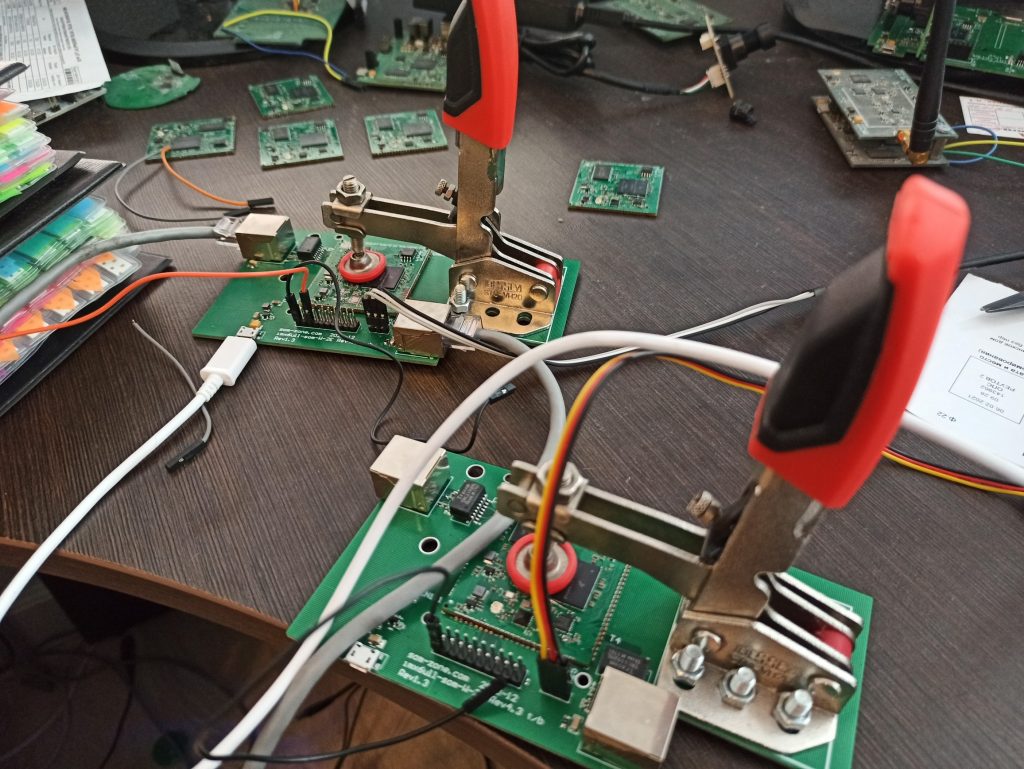
One of the testbench loaded with SoM having both PHY IC soldered. Another testbench loaded with single PHY IC soldered SoM module.
At least we have working link under U-boot so we can update firmware of device via TFTP.
As you remember we got working single PHY IC and was reading registers value using u-boot’s mii command. A similar command was sorely lacking under Linux. So we started with searching any utilitiy giving same functionality under Linux and found it here.
Step 3. Adding phytool package.
Clone project and create phytool package folder:
$ cd imx6ull-openwrt
$ mkdir package/phytool
$ cd package/phytool
include $(TOPDIR)/rules.mk
PKG_NAME:=phytool
PKG_VERSION:=1.0
PKG_RELEASE:=1
PKG_BUILD_DIR:=$(BUILD_DIR)/phytool-$(PKG_VERSION)
include $(INCLUDE_DIR)/package.mk
define Package/phytool
SECTION:=examples
CATEGORY:=Examples
TITLE:=PHY registers accessing via MDIO
endef
define Package/phytool/description
PHY registers accessing via MDIO
endef
define Build/Prepare
mkdir -p $(PKG_BUILD_DIR)
cp ./src/* $(PKG_BUILD_DIR)/
$(Build/Patch)
endef
define Build/Compile
$(MAKE) -C $(PKG_BUILD_DIR) CC=”$(TARGET_CC)” CFLAGS=”$(TARGET_CFLAGS)” LDFLAGS=”$(TARGET_LDFLAGS)”
endef
define Package/phytool/install
$(INSTALL_DIR) $(1)/usr/bin
$(INSTALL_BIN) $(PKG_BUILD_DIR)/phytool $(1)/usr/bin
endef
$(eval $(call BuildPackage,phytool))
$ git clone https://github.com/wkz/phytool.git src
make[1] package/phytool/compile
make[2] -C package/libs/toolchain compile
make[2] -C package/phytool compile
as expected proper PHY registers value on SoM with single PHY IC:
ieee-phy: reg:BMCR(0x00) val:0x3100
flags: -reset -loopback +aneg-enable -power-down -isolate -aneg-restart -collision-test
speed: 100-full
root@OpenWrt:/# phytool eth0/0/1
ieee-phy: reg:BMSR(0x01) val:0x7849
capabilities: -100-b4 +100-f +100-h +10-f +10-h -100-t2-f -100-t2-h
flags: -ext-status -aneg-complete -remote-fault +aneg-capable -link -jabber +ext-register
root@OpenWrt:/# phytool eth0/0/2
ieee-phy: reg:0x02 val:0x0022
root@OpenWrt:/# phytool eth0/0/3
ieee-phy: reg:0x03 val:0x1561
Step 4. DTS modification.
fec1 node presents Fast Ethernet Controller
&fec1 {
pinctrl-names = “default”;
pinctrl-0 = <&pinctrl_enet1>;
phy-mode = “rmii”;
phy-handle = <ðphy0>;
status = “okay”;
mdio {
#address-cells = <1>;
#size-cells = <0>;
ethphy0: ethernet-phy@0 {
compatible = “ethernet-phy-ieee802.3-c22”;
reg = <0>;
};
};
};
mdio presents mdio serial interface used for communication between MAC controller (MCU) and PHY IC for configuration purposes. Currently single IC exist on that bus presented by ethphy0 node with address 0. Address of KSZ8081 must be implemended on circuit design stage. Table 2-2 at page 9 of datasheet explains how it can be done.
Before adding second fec node existing one must be modified according to changes made in new PCB revision – specifically RESET pin GPIO connected to MCU:
phy-reset-duration = <10>;
phy-reset-post-delay = <50>;
phy-reset-duration and phy-reset-post-delay used to configure reset delay duration and duration of delay after reset in milliseconds. That values should be bigger that minimum applicable delays for specific IC described in datasheet for that IC.
phy-reset-gpios used to set specific GPIO of MCU connected to RST pin of PHY IC. LCD_DATA_13 in our case. GPIO_ACTIVE_LOW configures active signal level (LOW) to perform reset of PHY IC. E.g. reset pin should be driven LOW to perform a reset and remains HIGH in normal operation mode. LOW and HIGH are signal’s voltage levels – 0v and 3.3V.
LCD_DATA_13 pin of MCU must be configured as simple GPIO to drive reset pin of IC so gpio3 18 is number of that pin. All MCU gpios distributed to few GPIO controllers. Each of them controls up to 32 gpio. Exact gpio number of each MCU’s pad can be determined by following iomux map:

just find pad you interested in.
After that we need to add another on fec node describing second PHY IC:
pinctrl-names = “default”;
pinctrl-0 = <&pinctrl_enet2>;
phy-mode = “rmii”;
phy-handle = <ðphy1>;
phy-reset-gpios = <&gpio3 5 GPIO_ACTIVE_LOW>;
phy-reset-duration = <10>;
phy-reset-post-delay = <50>;
status = “okay”;
};
It looks much simplier rather than fec1 node. No need to describe mdio bus as it is already described in fec1 (same MDIO bus shared between two PHY IC). LCD_DATA0 (gpio3 5) pad of MCU connected to reset pin of PHY IC. phy-handle pointed to ethphy1 node not existing in DTS yet so it should be added:
compatible = “ethernet-phy-ieee802.3-c22”;
reg = <3>;
clocks = <&clks IMX6UL_CLK_ENET2_REF>;
clock-names = “rmii-ref”;
};
right after already existing ethphy0 node. Here reg = <3> determines PHY IC address on MDIO bus (Configurable PHY addresses are: 0h, 3h, 4h or 7h as explained in datasheet).
pinctrl-0 points to pinctrl_enet2 need to be implemented too:
fsl,pins = <
MX6UL_PAD_ENET2_RX_EN__ENET2_RX_EN 0x1b0b0
MX6UL_PAD_ENET2_RX_ER__ENET2_RX_ER 0x1b0b0
MX6UL_PAD_ENET2_RX_DATA0__ENET2_RDATA00 0x1b0b0
MX6UL_PAD_ENET2_RX_DATA1__ENET2_RDATA01 0x1b0b0
MX6UL_PAD_ENET2_TX_EN__ENET2_TX_EN 0x1b0b0
MX6UL_PAD_ENET2_TX_DATA0__ENET2_TDATA00 0x1b0b0
MX6UL_PAD_ENET2_TX_DATA1__ENET2_TDATA01 0x1b0b0
MX6UL_PAD_ENET2_TX_CLK__ENET2_REF_CLK2 0x4001b031
>;
};
pinctrl_enet2 should be placed right after pinctrl_enet1 node.
And the last one change – pinctrl_enet1 need to be modified by adding by adding two more pins describing MDIO bus used for communication with PHY ICs:
MX6UL_PAD_GPIO1_IO06__ENET1_MDIO 0x1b0b0
It might be confusing – where all this magic numbers and pad definitions taken from. As linux not well documented – the only way to understand it – research in existing source code base. I a case of DTS just search for already existing dts samples:
./build_dir/host/u-boot-2018.03/arch/arm/dts/imx6ull-14×14-evk.dts
./build_dir/toolchain-arm_cortex-a7+neon-vfpv4_gcc-7.5.0_musl_eabi/linux-4.14.199/arch/arm/boot/dts/imx6ull-14×14-evk.dts
./build_dir/target-arm_cortex-a7+neon-vfpv4_musl_eabi/u-boot-wirelessroad_ecspi3/u-boot-2017.07/arch/arm/dts/imx6ull-14×14-evk.dts
./build_dir/target-arm_cortex-a7+neon-vfpv4_musl_eabi/u-boot-2018.03/arch/arm/dts/imx6ull-14×14-evk.dts
./build_dir/target-arm_cortex-a7+neon-vfpv4_musl_eabi/linux-imx6ull_cortexa7/linux-4.14.199/arch/arm/boot/dts/imx6ull-14×14-evk.dts