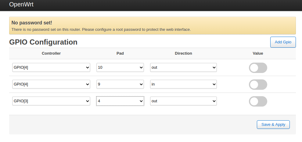
imx6 gpio configuration and control web interface.
Here described step of development imx6 gpio configuration and control web interface using OpenWrt driven IMX6ULL SoM.
As a result following web interface will be implemented:

MR that implements this functionaly may be found here.
If you don’t have time to read article and just want to get such UI control interface – just clone or download that repository and compile it using single command:
DTS modification.
First step to add support for new hardware is DTS modification. As GPIO is probably the easiest hardware to add support for each pad you want to use as GPIO require just one single line to be added in DTS:
MX6UL_PAD_NAND_DATA03__GPIO4_IO05 0x000010B0 /* General GPIO */
MX6UL_PAD_NAND_READY_B__GPIO4_IO12 0x000010B0 /* General GPIO */
MX6UL_PAD_NAND_CLE__GPIO4_IO15 0x000010B0 /* General GPIO */
MX6UL_PAD_NAND_CE0_B__GPIO4_IO13 0x000010B0 /* General GPIO */
MX6UL_PAD_NAND_CE1_B__GPIO4_IO14 0x000010B0 /* General GPIO */
MX6UL_PAD_NAND_WP_B__GPIO4_IO11 0x000010B0 /* General GPIO */
MX6UL_PAD_NAND_DQS__GPIO4_IO16 0x000010B0 /* General GPIO */
MX6UL_PAD_LCD_DATA09__GPIO3_IO14 0x000010B0 /* General GPIO */
MX6UL_PAD_NAND_DATA00__GPIO4_IO02 0x000010B0 /* General GPIO */
MX6UL_PAD_NAND_RE_B__GPIO4_IO00 0x000010B0 /* General GPIO */
MX6UL_PAD_NAND_WE_B__GPIO4_IO01 0x000010B0 /* General GPIO */
MX6UL_PAD_NAND_DATA01__GPIO4_IO03 0x000010B0 /* General GPIO */
MX6UL_PAD_NAND_DATA02__GPIO4_IO04 0x000010B0 /* General GPIO */
Pads naming is following:
as each PAD of CPU might be configured for usage with different functionality. Resulted file might be found here.
That’s it. The rest of development process to be done on application layer.
Manual GPIO configuration and control.
Let’s compile image with modified DTS:
copy it to the device:
and update firmware:
GPIO configuration at user space is pretty simple. First you have to export GPIO. For example:
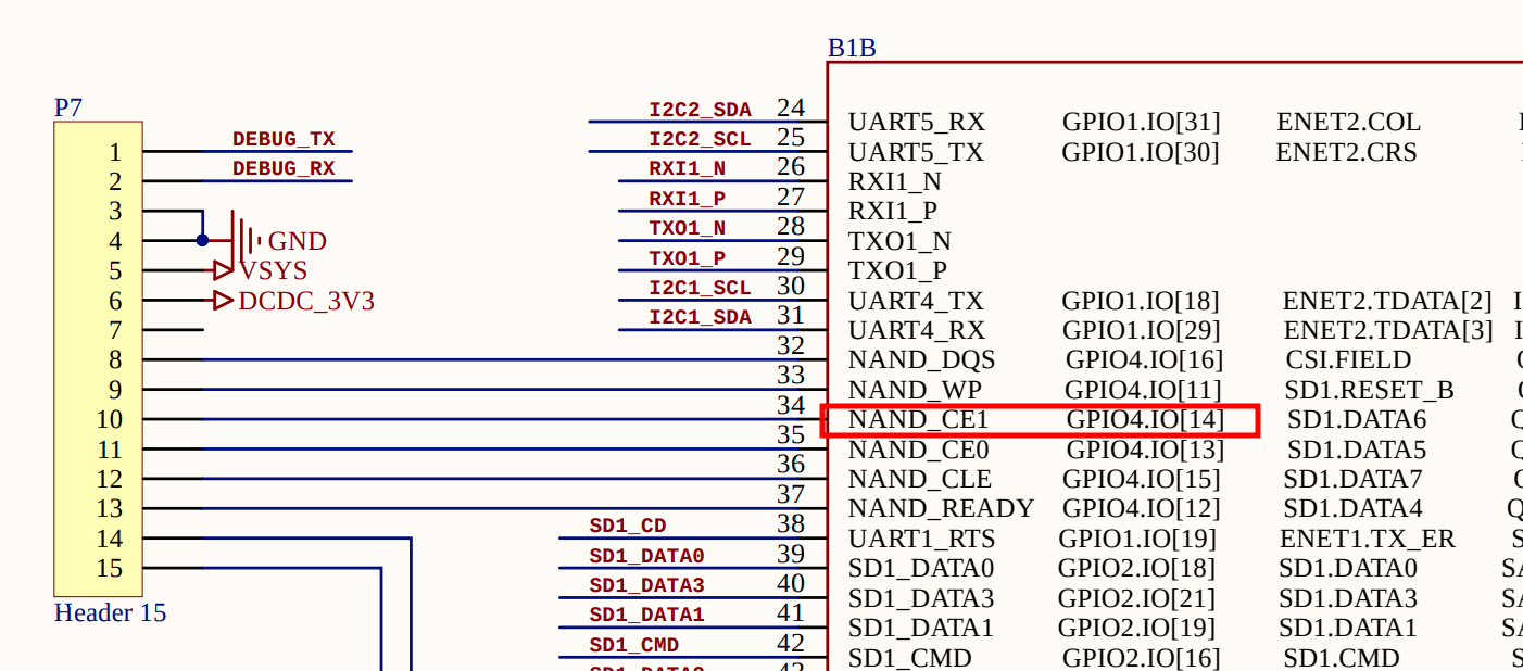
The number of each GPIO might be gotten by simple calculation. First you have to look at schematic. Each pin of IMX6 SoM marked with set of available interfaces current pad might be configured for. GPIO as well.
Let’s suppose we want to use NAND_CE1 as general purpoce input/output routed to header P7 of development board. That PAD number 14 is part of controller number 4.

So to get PAD number you can use at user space you have to subtract 1 from PAD controller number ( 4-1 = 3, numbering starts from zero), multiple resulted value to 32 (3 * 32 = 96) as each PAD controller contains up to 32 pins (some pads from this 32 pin might be missed). And finally to get resulted value you have to add pad number from it’s name (96 + 14 = 110). E.g. formula is following:
# linux user space number = ( (x – 1) * 32 + y)
So now we know PAD number to export it:
then you have to set GPIO direction. To use pad as output to drive for example LEDs, relays, to generate output signals:
or as input to control value of buttons, catch input signals:
To set value of output GPIO:
# echo 0 > /sys/class/gpio/gpio110/value
To read value of input GPIO:
List of already used pins might be found at:
or:
C application
Except bash commands there are other gpio configuration/control methods exists. One of them – writing C application explained in this chapter. Another one – using web interface will be explained in next chapter. We will pack that application as package. Source code might be found here. Package contains: Makefile and source code files (files folder better to be placed in luci-gpio package so ignore it for now). Usage of gpio_conf.json will be explained later.
C application itself is pretty simple:
#include <stdio.h>
#include <fcntl.h>
#include <unistd.h>
#define OUT_AMOUNT 2
int main(int argc, char *argv[])
{
int out[OUT_AMOUNT];
printf(“\nHello, World!\r\n”);
// export GPIO
fd = open(“/sys/class/gpio/export”, O_WRONLY);
write(fd, “112”, 2);
close(fd);
// Configure as output
fd = open(“/sys/class/gpio/gpio112/direction”, O_WRONLY);
write(fd, “out”, 3);
close(fd);
// export GPIO
fd = open(“/sys/class/gpio/export”, O_WRONLY);
write(fd, “107”, 2);
close(fd);
// Configure as output
fd = open(“/sys/class/gpio/gpio107/direction”, O_WRONLY);
write(fd, “out”, 3);
close(fd);
out[0] = open(“/sys/class/gpio/gpio112/value”, O_WRONLY | O_SYNC);
out[1] = open(“/sys/class/gpio/gpio107/value”, O_WRONLY | O_SYNC);
while(1) {
for(int i=0; i<OUT_AMOUNT; i++) {
write(out[i], “0”, 1);
usleep(100000);
write(out[i], “1”, 1);
usleep(100000);
}
}
}
No need to recompile whole image to test it on hardware. Compile package only:
resulted binary might be found here:
Makefile gpio gpio.c gpio.o ipkg-arm_cortex-a7_neon-vfpv4
copy executable file gpio via scp and run it.
Next method to control GPIO is using web interface. Gives highest flexibility.
Web interface.
Backend.
Similar to C application it will be packed in package. We will use existing OpenWrt web interface called LuCi. You probably seen it in your home router. IMX6 will act as backend for users accessing web interface from browser. Makefile is pretty simple. Source code will have just two files: gpio.lua – lua script that might be considered as Backend part of solution. It is responsible for handling queries from Frontend.
Each luci module must have function called index that responsible for registration new module of web interface with its API – list of supported URLs that current module to be handle:
function index()
{
entry( {“admin”, “gpio”}, template(“gpio”), _(“Gpio”), 99)
entry( {“admin”, “gpio”, “configuration_get”}, call(“gpio_configuration_get”)).leaf = true
entry( {“admin”, “gpio”, “configuration_set”}, post(“gpio_configuration_set”)).leaf = true
entry( {“admin”, “gpio”, “value_get”}, call(“gpio_value_get”)).leaf = true
entry( {“admin”, “gpio”, “value_set”}, post(“gpio_value_set”)).leaf = true
}
Two endpoints gpio_configuration_get and gpio_configuration_set to configure GPIOs.
Rest two: gpio_value_get andgpio_value_set – to control GPIOs state. Body of each function might be found here. If you not familiar with luci – you can get first introduction with it in 15 minutes. Just pass through this article and you will be able to make write simple scripts and modify existing for sure. Pretty simple but powerful language. Main advantage of using lua (as well as bash, as well as JavaScript used for Frontend development) – is in openwrt – is ability to develop software right on the target machine almost without cross compilation. Later will be explained how to achieve that. In fact lua and JS opens door to the world of embedded software development for developers not familiar with embed. For tasks that doesn’t require high timings you should consider of using scripting tools (bash/lua/js) instead of C applications for sure.
Frontend.
Is also simple enough and contains just single gpio.htm file written on HTML for page body generation, JavaScript for data processing and CSS inline styling. Simple task to implement for any web developer. Rest of the styling that can’t be implemented using inline code might be found here.
Development tricks.
You can recompile whole image and update firmware of target machine but to speed up development process (delivery of code changes) you better to develop SW right on target machine.
- create gpio.lua in /usr/lib/lua/luci/controller folder. It will be Backend part of solution:
- create gpio.htm in /usr/lib/lua/luci/view folder. It will be Frontend part of solution:
- create switch.css in /www/luci-static/resources folder for styling of UI:
You allowed to give any names to this files but make sure that .lua file name is same as module name provided in the body of that file and it is similar to .htm file name.
Then each time you made changes .htm or .css files you have to update web page in your browse to see them.
For changes in .lua file you have to clear cashe files:
Don’t forget to use developer tools of browser:

Here how result looks like:
Join our telegram channel to see more photos and videos.

